Part 1: Manufacturing High-Precision Parts with CNC Machining (800 words)
1.1 Equipment Selection for High-Precision Machining (250 words)
High-precision CNC machining (tolerances ≤ ±0.005mm) starts with rigid machine tools, as structural flex under cutting forces directly degrades accuracy. Two common machine structures dominate:
Linear-guideway machines: Use precision steel rails with ball bearings, enabling faster feed rates (up to 60 m/min) and lower friction. Their rigidity is sufficient for light-to-medium cutting (e.g., aluminum electronics parts) and delivers positioning accuracy of ±0.001mm, making them suitable for high-speed precision tasks.
Box-way machines: Feature heavy-duty cast-iron beds with rectangular guideways, offering rigidity 30–50% higher than linear-guideway models. Ideal for heavy cutting (e.g., titanium alloy machining), they minimize vibration-induced errors—critical for parts requiring ±0.002mm tolerance (e.g., aerospace fasteners).
Advanced control systems further enhance precision. Top-tier systems like Fanuc 31i-B and Siemens Sinumerik ONE integrate:
- High-resolution encoders: 10,000–1,000,000 pulses per revolution (ppr) for axis positioning—1,000,000 ppr encoders reduce position error to ±0.0001mm.
- Real-time error compensation: Dynamic compensation for thermal expansion, backlash, and geometric deviations (e.g., pitch error). For example, Mazak’s Smart Thermal Shield system cuts thermal-induced errors by 80%, maintaining ±0.003mm tolerance even in 10℃ temperature fluctuations.
1.2 Tooling for High-Precision Parts (250 words)
High-quality cutting tools are non-negotiable for maintaining precision over extended runs. Carbide tools (e.g., WC-Co alloys) outperform high-speed steel (HSS) by 5–10x in wear resistance: a carbide end mill can machine 500 aluminum parts (±0.005mm tolerance) before regrinding, vs. 50 parts for HSS. Diamond-coated carbide tools excel in non-ferrous materials (e.g., aluminum, copper), with a surface finish (Ra) of 0.2–0.4μm—critical for optical or fluidic components.
Tool geometry is tailored to material and precision needs:
- Rake angle: 10–15° for aluminum (reduces cutting force, minimizing part deflection);5–8° for hardened steel (enhances edge strength).
- Edge radius: 0.01–0.02mm for fine finishing (avoids burrs), 0.05–0.1mm for roughing (extends tool life).
Tool setting and calibration use precision probes (e.g., Renishaw OMP40-2) with ±0.0005mm accuracy. These probes measure tool length, radius, and runout before machining, automatically updating the CNC system’s tool offset database. Calibration every 50–100 parts prevents tool wear-induced errors—for example, a 0.001mm tool wear can be compensated in real time, keeping part tolerance within ±0.003mm.
1.3 Process Planning for High-Precision Machining (300 words)
Optimized machining sequences prioritize minimizing residual stress and deformation. A typical sequence for a precision aluminum bracket (±0.004mm tolerance) includes:
- Rough machining: Remove 70–80% of excess material at low feed rates (50–100 mm/min) to reduce heat buildup.
- Stress relief: Natural aging (24–48 hours at 25℃) or artificial aging (120℃ for 2 hours) to eliminate machining-induced stress—this cuts post-finishing deformation by 60%.
- Semi-finishing: Remove 10–15% of material at moderate feed rates (150–200 mm/min), leaving a 0.1–0.2mm finishing allowance.
- Finishing: High-speed cutting (300–500 mm/min) with small depth of cut (0.02–0.05mm) to achieve final tolerance.
Coolant and lubricant selection directly impacts precision. For different materials:
- Steel (HRC 30–40): Emulsified coolants (5–10% concentration) with EP (extreme pressure) additives—reduce cutting temperature by 40–50℃, preventing thermal expansion of the part.
- Titanium alloy (Ti-6Al-4V): Oil-based lubricants (viscosity 100–150 cSt) or cryogenic cooling (liquid nitrogen at -196℃)—minimize tool wear and part oxidation, maintaining ±0.002mm tolerance.
- Aluminum (6061-T6): High-pressure coolant (70–100 bar) directed at the cutting zone—breaks up chips and cools the tool, reducing surface roughness from Ra 1.6μm to Ra 0.8μm.
Additionally, fixture design uses low-deformation clamping (e.g., vacuum chucks for thin-walled parts) to avoid part deflection. A vacuum chuck with 0.001mm flatness can hold a 1mm-thick aluminum sheet without warping, ensuring machining accuracy.
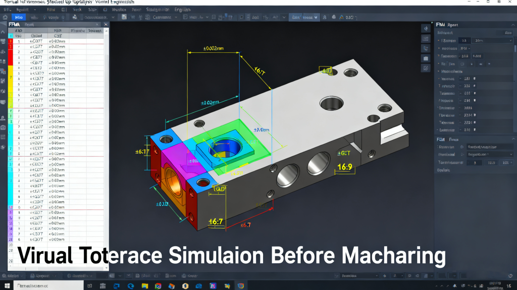
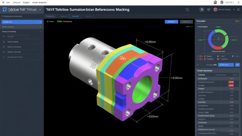
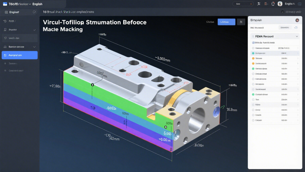
Part 2: Reducing Tolerances in CNC-Machined Parts (600 words)
2.1 Understanding Tolerance Sources (200 words)
Tolerances (deviations from design dimensions) stem from two core sources: machine-related factors and process-related factors.
Machine-related tolerances include:
Backlash: Clearance in lead screws or gearboxes (typically 0.001–0.003mm for high-precision machines). For example, a lead screw with 0.002mm backlash can cause a 0.002mm positional error when reversing axis direction—critical for parts with symmetric features.
Thermal expansion: Machine components (bed, spindle, rails) expand with temperature changes. A cast-iron bed expands 0.01mm per meter for every 1℃ temperature rise; a 5℃ fluctuation can introduce a 0.05mm error in a 5m-long machine.
Geometric inaccuracies: Misalignment of axes (e.g., X-axis parallelism error of 0.001mm/m) or spindle runout (0.0005–0.001mm for high-precision spindles).
Process-related tolerances arise from:
- Cutting forces: High cutting forces (e.g., 500–1000 N for steel machining) cause part deflection. A 20mm-diameter steel shaft may deflect 0.005–0.01mm under heavy cutting, leading to dimensional errors.
- Tool wear: A worn tool (e.g., 0.003mm edge wear) produces parts with reduced accuracy—for example, a worn end mill may machine a hole 0.003mm larger than the design size.
- Chip formation: Built-up edge (BUE) on the tool (common in aluminum machining) leaves irregularities on the part surface, increasing tolerance deviation by 0.002–0.004mm.
2.2 Strategies for Tolerance Reduction (400 words)
Thermal management is critical to minimizing temperature-induced errors. Key measures include:
- Active cooling systems: Spindle cooling (oil circulation with ±0.1℃ temperature control) and bed cooling (water jackets) reduce thermal expansion. For example, Haas’s Thermo-Friendly™ design cuts spindle thermal growth by 90%, limiting error to ±0.0005mm.
- Environmental control: Machining rooms maintained at 20±1℃ with 50±5% humidity—prevents temperature fluctuations that affect machine and part dimensions.
- Temperature-compensated control: CNC systems (e.g., Okuma’s Thermo Active Stabilizer) use sensors to monitor temperatures of the bed, spindle, and ambient air, automatically adjusting tool paths to offset expansion. This reduces thermal errors by 70–80%, maintaining ±0.002mm tolerance.
Error compensation techniques address machine and process inaccuracies:
- Backlash compensation: The CNC system is programmed to overshoot the target position by the measured backlash (e.g., 0.002mm) when reversing axes, eliminating positional error. Laser interferometers (e.g., Renishaw XL-80) measure backlash with ±0.0001mm accuracy for precise compensation.
- Geometric error compensation: Using a laser interferometer or ballbar (e.g., Renishaw QC20-W) to map 21 geometric errors (e.g., pitch, yaw, roll) of the machine. The CNC system then applies software compensation—for example, a pitch error of 0.001mm/m is offset by adjusting the axis position at each measurement point.
- Tool wear compensation: In-process probing measures the part dimensions periodically (every 20–50 parts), and the system updates tool offsets to account for wear. For a tool with 0.002mm wear, the offset is adjusted by -0.002mm, ensuring subsequent parts meet tolerance.
Additionally, material selection impacts tolerance retention. Pre-hardened materials (e.g., 4140 steel HRC 28–32) are less prone to deformation than annealed materials, while low-thermal-expansion alloys (e.g., Invar 36, expansion coefficient 1.2×10⁻⁶/℃) are ideal for parts used in temperature-variable environments (e.g., aerospace sensors).
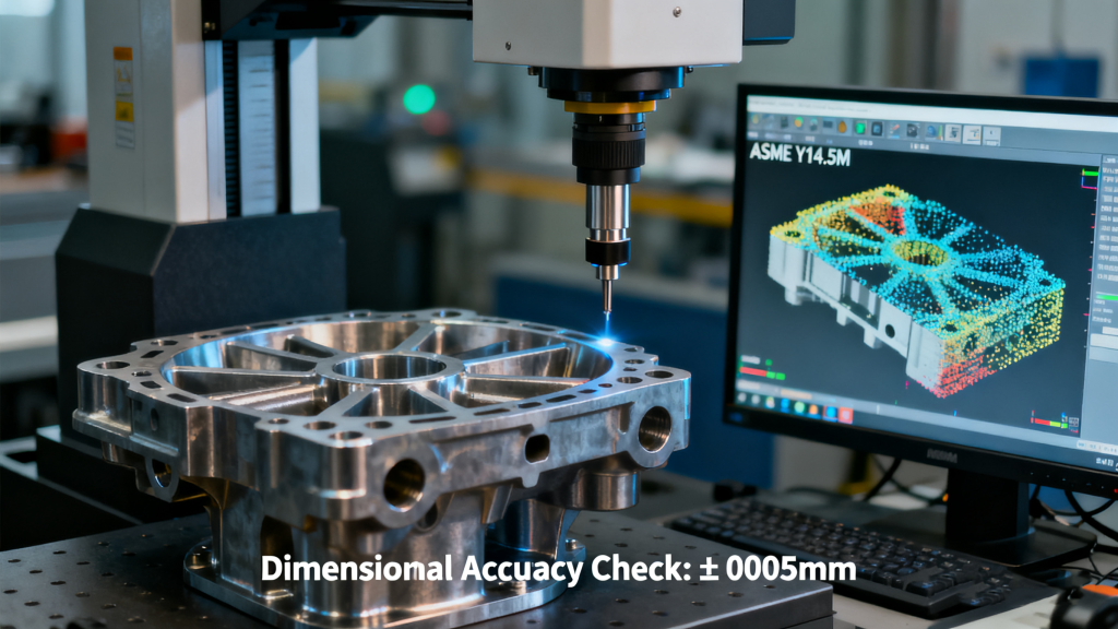
Part 3: Conducting Quality Inspections for High-Precision Parts (600 words)

3.1 In-process Quality Inspections (200 words)
In-process inspections (during machining) catch errors early, reducing scrap and rework. The primary tool is on-machine probing (OMP), integrated into the CNC spindle or tool turret.
Probing systems (e.g., Renishaw OMP60, accuracy ±0.0005mm) perform two key tasks:
- Part setup verification: After clamping the part, the probe measures reference features (e.g., holes, edges) to confirm alignment with the machine coordinate system. If the part is misaligned by 0.003mm, the system adjusts the work offset to correct it—critical for batch production.
- In-cycle dimension checks: After semi-finishing or key machining steps, the probe measures critical dimensions (e.g., hole diameter, feature spacing). For example, a precision gear (±0.002mm tooth profile tolerance) is probed after machining 10 teeth; if a tooth is 0.001mm undersized, the tool offset is adjusted before machining the remaining teeth.
Benefits of in-process inspection include:
- Reduced scrap rate: A medical device manufacturer using OMP cut scrap from 3% to 0.5% for titanium implants (±0.003mm tolerance).
- Minimized rework: Early error detection avoids fully machining out-of-tolerance parts—saving 2–3 hours of machining time per part.
- Real-time process adjustment: Probing data identifies trends (e.g., tool wear accelerating), allowing proactive maintenance (e.g., tool replacement) before tolerance is breached.
3.2 Post-process Quality Inspections (300 words)
Post-process inspections (after machining) verify final part compliance with design specs. Two primary methods dominate:
Coordinate Measuring Machines (CMMs) are the gold standard for 3D dimensional inspection. High-precision CMMs (e.g., Zeiss Contura G2, accuracy ±0.0008mm; Hexagon Absolute Arm, accuracy ±0.0015mm) use touch probes (ruby tips, diameter 0.5–2mm) to measure hundreds of points on the part. Key capabilities include:
- Geometric dimensioning and tolerancing (GD&T) verification: Checking features like flatness (≤0.001mm), perpendicularity (≤0.002mm), and position (±0.003mm) per ASME Y14.5 standards.
- Surface roughness measurement: Integrating stylus profilometers (e.g., Taylor Hobson Talysurf) to measure Ra (0.02–1.6μm) and Rz (0.1–6.3μm) for critical surfaces (e.g., sealing faces).
Optical inspection methods excel at fast, non-contact inspection, ideal for small, complex parts or high-volume production:
- Vision systems (e.g., Keyence IM-7000, accuracy ±0.0005mm): Use high-resolution cameras (5–20 MP) and software to analyze 2D features (e.g., hole diameter, edge sharpness). They inspect parts in 0.1–1 second—10–50x faster than CMMs for simple geometries.
- Laser scanning (e.g., GOM ATOS Q, accuracy ±0.001mm): Captures 3D point clouds (millions of points per second) to compare the part to its CAD model. Ideal for complex surfaces (e.g., turbine blades) or parts with free-form features, detecting deviations as small as ±0.0005mm.
Post-process inspection requires calibration to ensure accuracy: CMMs are calibrated annually with traceable standards (e.g., NIST-certified gauge blocks), while optical systems are checked weekly with calibration plates (known dimensions ±0.0001mm).
3.3 Statistical Process Control (SPC) (100 words)
SPC monitors machining processes to prevent out-of-tolerance parts. Key steps include:
- Data collection: Measuring 5–10 critical dimensions per part (e.g., hole diameter) at regular intervals (every 1–2 hours).
- Control chart analysis: Plotting data on X-R charts (average and range) to track variation. If points exceed control limits (e.g., 3σ from the mean), the process is adjusted (e.g., tool replacement, thermal compensation).
- Process capability analysis: Calculating Cpk (process capability index)—a Cpk ≥1.33 indicates the process meets ±0.005mm tolerance, while Cpk ≥1.67 ensures compliance with ±0.002mm tolerance.
SPC reduces variation by 30–40%, ensuring consistent precision for high-volume production (e.g., automotive sensors, electronics components).
FAQs (300 words)
1. How much does high-precision CNC machining equipment cost?
Costs vary by capability:
- Entry-level high-precision (±0.005mm): 3-axis mills (e.g., Haas DT-1) cost \(50,000–\)100,000; ideal for small-batch parts (e.g., prototype components).
- Mid-range (±0.002mm): 5-axis machines (e.g., Okuma Genos M560-V) cost \(200,000–\)350,000; suitable for aerospace and medical parts.
- Top-tier (±0.0005mm): Multi-axis machines with advanced controls (e.g., DMG MORI DMU 50 ecoline) cost \(400,000–\)800,000; used for ultra-precision parts (e.g., optical lenses, microelectronics).
Additional costs (probes, cooling systems) add 10–20% of the machine price.
2. Can all types of materials be machined to high precision using CNC?
Most engineering materials can, but difficulty varies:
- Metals: Aluminum (6061-T6), steel (4140), and titanium (Ti-6Al-4V) are easily machined to ±0.002mm with standard tools.
- Plastics: PEEK and Delrin can achieve ±0.003mm, but require low cutting forces to avoid warping.
- Ceramics: Alumina (Al₂O₃) and zirconia (ZrO₂) need diamond tools and ultrasonic-assisted machining to reach ±0.002mm—higher cost and longer cycle times.
Brittle materials (e.g., glass) require specialized processes (e.g., laser machining) for high precision.
3. How often should quality inspections be conducted during high-precision CNC machining?
Frequency depends on production volume and part criticality:
- Low-volume (1–10 parts, high-value): 100% in-process probing (after each key step) and 100% post-process CMM inspection (e.g., aerospace prototypes).
- Medium-volume (10–100 parts): In-process probing every 5–10 parts, post-process sampling (AQL 1.0, per ISO 2859) with CMM or vision systems.
- High-volume (1000+ parts): In-process probing every 20–50 parts, SPC monitoring (5 parts/hour), and post-process spot checks (1% of production) with optical scanners.
Critical parts (e.g., medical implants) require 100% inspection regardless of volume.
LSI and NLP Keywords and Related Vocabulary
LSI Keywords
High-precision CNC machining equipment
Tooling for high-precision parts in CNC machining
Process planning for high-accuracy CNC parts
Tolerance reduction in CNC-machined parts
Quality inspections for high-precision CNC components
In-process inspection in high-precision CNC machining
Post-process inspection of high-precision CNC parts
NLP Keywords
Manufacturing high-precision parts with CNC
Reducing tolerances in CNC machining
Conducting quality checks on high-precision CNC parts
High-precision CNC machining techniques
Quality control in high-precision CNC manufacturing
Related Vocabulary
CNC machine rigidity (box-way, linear-guideway), high-resolution encoders, real-time error compensation, carbide cutting tools, diamond-coated tools, tool setting probes, machining sequences (roughing, semi-finishing, finishing), coolant selection (emulsified, oil-based, cryogenic), thermal expansion, backlash compensation, geometric error compensation, coordinate measuring machines (CMMs), optical inspection (vision systems, laser scanning), statistical process control (SPC), control charts (X-R), process capability index (Cpk), GD&T (geometric dimensioning and tolerancing), surface roughness (Ra, Rz)