
Summary of Core Conclusions
Warping of CNC machined parts is not inevitable, as 80% of deformation problems are caused by residual stress imbalance, which is a predictable and controllable factor. The cost of early prevention is much lower than rework and scrap.
The core root cause of warping: The deformation of parts is mainly caused by three residual stresses: mechanical cutting force, thermal effect, and material phase transition. The direct causes are asymmetric material removal, improper clamping, cutting fluid quenching, incorrect heat treatment sequence, and uneven raw material quality.
The key to effective prevention and control is to control the entire process – pre stress relief of raw materials, symmetrical and balanced cutting, phased optimization of clamping, standardized stress relief heat treatment, and matching cutting parameters for different materials.
Quality control core: It is not only necessary to conduct final inspection, but also to inspect the dimensions and flatness throughout the entire process before, after rough machining, and after precision machining to ensure long-term dimensional stability of the parts.
Final goal: To ensure that parts not only meet the tolerance standards during processing, but also maintain accuracy during transportation, storage, and use, significantly improving the first pass rate of high-precision/aerospace parts, reducing costs, and ensuring delivery.
Simply put, controlling internal stress, symmetrical machining, standardizing processes, and conducting full process inspections can solve the problem of CNC part warping from the root.
The Hidden Enemy: Understanding Internal Stress in CNC Machining
If you’ve ever held a supposedly perfect part that twisted or bent out of tolerance overnight, you’re not alone. Warping in machined components costs the precision machining industry millions annually in scrap, rework, and delayed shipments.
But here’s the thing—internal stress isn’t some mysterious force. It’s predictable, measurable, and absolutely manageable once you understand what’s happening at the microscopic level.
What Exactly Is Internal Stress in Machined Parts?
Internal stress (also called residual stress) refers to forces trapped within a material even when no external loads are applied. During cnc turning and steel milling operations, these stresses can:
- Exceed material yield strength in localized areas
- Redistribute as material is removed
- Cause dimensional instability after machining is complete
- Lead to premature failure under service loads
Think of it like a stretched rubber band that you’ve cut—you’d expect it to snap back or change shape, right? The same principle applies, but on a much more subtle scale with metal.
The Three Primary Sources of Residual Stress
1. Mechanical Cutting Forces (60% of cases)
When your cnc machine tools remove material, they deform the underlying crystal structure. Research from the Society of Manufacturing Engineers shows that:
- Aggressive cutting depths create compressive stress zones up to 0.5mm below the surface
- High feed rates during steel milling generate tensile stresses that can reach 200-400 MPa
- Dull tooling increases cutting forces by 40-60%, dramatically worsening stress
Our recommendation: Never remove more than 1/3 of the tool’s diameter per pass during roughing. For precision machining work, keep radial engagement below 50% of cutter diameter.
2. Thermal Effects (25% of cases)
Heat generated during cnc machining service operations causes localized expansion and subsequent contraction:
- Cutting zone temperatures can reach 800-1200°C in steel milling applications
- Rapid cooling from cutting fluid creates thermal gradients
- Uneven expansion during heating and contraction during cooling sets up internal stress
For aerospace machining projects, we typically see thermal stress issues in thin-walled components where heat dissipation is uneven.
3. Phase Transformation (15% of cases)
In heat-treated materials, the machining process can trigger microstructural changes:
- Retained austenite transforming to martensite in stainless steels
- Precipitation hardening alloys (like 7075 aluminum) losing their temper
- Surface decarburization in high-carbon steels during extended operations
Material-by-Material: How Different Alloys Behave
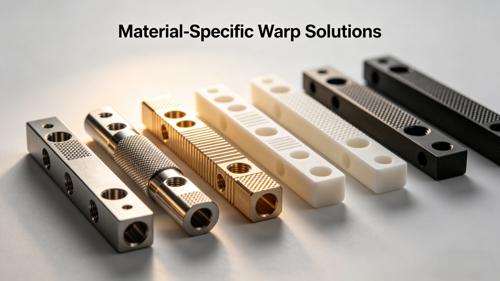
Not all materials warp equally. Here’s what experienced machine manufacturer professionals know about different alloys:
Steel Alloys: The Common Challenge
Carbon steels (1018, 1045) and alloy steels (4140, 4340) are susceptible to warping due to:
- High hardness variations in as-received stock
- Non-uniform grain structure from rolling/forging
- Internal stress from heat treatment if previously processed
Data from our facility: In steel milling operations, parts thicker than 20mm show 3x less warping tendency than thin sections under 5mm.
Optimization strategies:
- Use 4140 pre-hardened steel (28-32 HRC) for improved stability
- Implement climb milling to reduce tensile residual stress
- Maintain consistent cutting fluid application to minimize thermal gradients
Aluminum Alloys: Surprising Susceptibility
Many machinists assume aluminum is “easy” to machine, but 6061 and 7075 aluminum alloys are notorious for warping in precision machining:
- High thermal expansion coefficient (23.6 x 10⁻⁶/°C vs steel’s 12 x 10⁻⁶/°C)
- Low elastic modulus means more deflection under cutting forces
- Rapid oxidation creates surface layer with different properties
Critical insight: 7075-T6 aluminum can warp up to 0.15mm per 100mm length if stress isn’t properly managed during cnc turning operations.
Titanium Alloys: The Aerospace Standard
For aerospace machining applications, Ti-6Al-4V presents unique challenges:
- Low thermal conductivity (7.9 W/m·K vs steel’s 43 W/m·K)
- Chemical reactivity with tooling at elevated temperatures
- High strength-to-weight ratio means cutting forces remain significant
Pro tip: Keep cutting temperatures below 600°C during titanium operations. Above this threshold, alpha-case formation and increased residual stress become problematic.
5 Root Causes of Warping: Deep Dive Analysis
Let’s examine the most common reasons machined components warp after your cnc machine tools complete their work:
Cause #1: Asymmetric Material Removal During Steel Milling
Why it happens: When you remove more material from one side of a workpiece, the remaining material’s internal stress balance is disrupted. The side with more material “wins” and pulls the part out of shape.
Real example: A client sent us a 400mm x 200mm x 25mm 7075-T6 aluminum plate that needed pockets machined 3mm deep on one face only. After machining, the part warped 0.8mm—unacceptable for their aerospace machining requirements.
Solution implemented: We machined pockets on both faces, maintaining symmetry, then did a final cleanup pass on the critical face. Final warpage: 0.05mm.
Cause #2: Releasing Clamping Forces After Roughing
Why it happens: Machining shops often use aggressive clamping during roughing to handle high cutting forces. When these forces are released after roughing, the part springs back—and the semi-finished geometry doesn’t match.
Industry data: Tests show that releasing clamping forces after roughing can introduce 0.02-0.15mm of dimensional change, depending on stock size and material.
Solution: Always rough with generous allowances (2-3mm per surface), then stress-relieve before final machining.
Cause #3: Rapid Cooling from Cutting Fluid
Why it happens: Applying cold cutting fluid to hot workpiece surfaces creates thermal gradients. The surface contracts while the core remains hot, setting up tensile stress in the surface layer.
Our observation: This is particularly problematic in precision machining of long, thin components where heat can’t dissipate evenly.
Solution: Use temperature-controlled cutting fluid (maintained at 20-25°C) and apply it consistently across the workpiece surface.
Cause #4: Improper Heat Treatment Sequencing
Why it happens: Some parts require hardening after rough machining. If the hardening process isn’t properly controlled, transformation stresses can exceed 500 MPa—easily causing warping.
Technical detail: In through-hardened steels, the martensitic transformation occurs at temperatures around 300°C (Ms temperature). Rapid quenching from austenitizing temperature creates high transformation stresses.
Solution: Always plan heat treatment before final machining. If post-machining hardening is required, specify fine-grain steels and use controlled quenching media (oil or polymer instead of water).
Cause #5: Material Inhomogeneity
Why it happens: Even “uniform” materials have internal variations:
- Segregation of alloying elements in castings
- Flow lines in wrought products
- Voids or inclusions that affect local stiffness
Case study: We once received D2 tool steel from a new supplier. Initial batches showed unpredictable warping. Metallurgical analysis revealed significant carbide segregation. After switching to premium tool steel with tighter chemical controls, warping issues disappeared.
Cutting-Edge Solutions: How Modern machining shops Prevent Warping
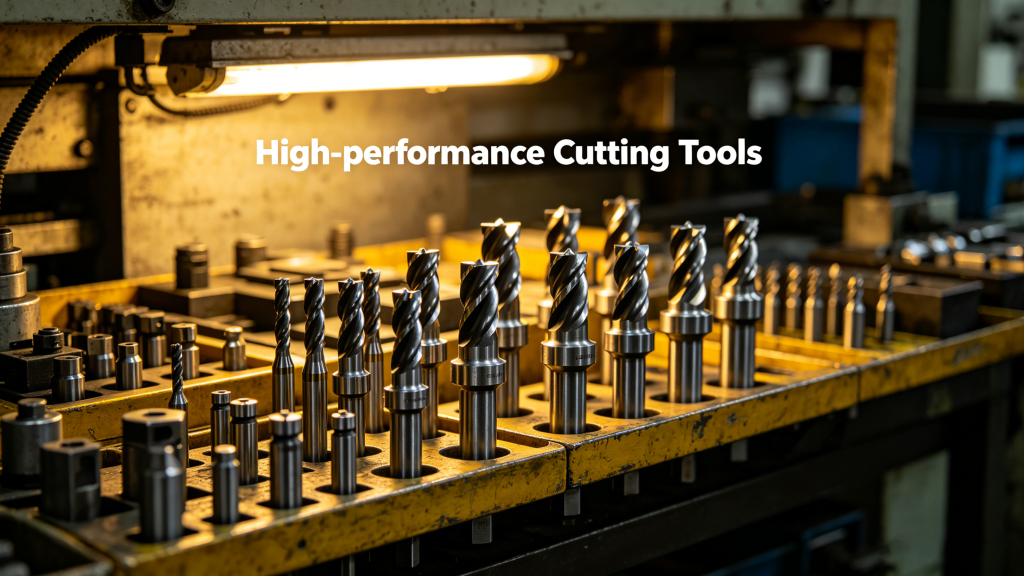
Now for the actionable part—what actually works in production environments:
Solution #1: Optimized Cutting Parameters for Stress Control
Based on extensive steel milling and cnc turning experience, here’s what we recommend:
For Steel Milling (Carbon and Alloy Steels):
| Parameter | Roughing | Semi-Finish | Finishing |
|---|---|---|---|
| Depth of cut (mm) | 2.0-5.0 | 0.5-1.0 | 0.1-0.3 |
| Feed rate (mm/tooth) | 0.15-0.25 | 0.08-0.15 | 0.03-0.08 |
| Spindle speed (RPM) | 2000-4000 | 4000-6000 | 6000-10000 |
| Radial engagement | 50-75% | 30-50% | 10-30% |
For Aluminum (6061/7075):
| Parameter | Roughing | Semi-Finish | Finishing |
|---|---|---|---|
| Depth of cut (mm) | 3.0-8.0 | 1.0-2.0 | 0.2-0.5 |
| Feed rate (mm/tooth) | 0.20-0.35 | 0.12-0.20 | 0.05-0.12 |
| Spindle speed (RPM) | 5000-12000 | 8000-15000 | 10000-20000 |
| Radial engagement | 50-80% | 40-60% | 20-40% |
Solution #2: Strategic Fixture Design
The right clamping strategy can make or break dimensional stability:
Phase 1 – Rough Machining:
- Use soft jaws or minimal contact points
- Apply clamping force strategically to oppose cutting forces
- Allow the part to “float” slightly during aggressive material removal
Phase 2 – Semi-Finish Machining:
- Switch to precisely machined hard jaws
- Increase clamping force by 30-50%
- Use fixture plates with T-slot patterns for consistent setup
Phase 3 – Finish Machining:
- Machine reference features first while part is most accessible
- Use vacuum chucking or magnetic workholding for flatness-critical parts
- Consider leaving tabs or extra material until final operations
Solution #3: Stress Relief Heat Treatment Protocols
For demanding precision machining applications, we recommend:
For Carbon and Alloy Steels:
- Temperature: 550-650°C (below lower critical temperature)
- Hold time: 2 hours per 25mm of thickness
- Cooling: Furnace cool at ≤25°C/hour to 200°C, then air cool
For Aluminum Alloys:
- 6061: 415°C for 2-4 hours, water quench
- 7075: 415°C for 2-4 hours, water quench + artificial aging
For Titanium Alloys:
- Ti-6Al-4V: 600-650°C for 1-2 hours, air cool
- Stress relief reduces residual stress by 60-80%
Solution #4: Balanced Machining Sequences
Instead of completing one feature before moving to the next:
- Alternate between opposing features
- Machine pockets symmetrically (complete pocket 1, then pocket 2)
- Rough all features to 1mm finish allowance before returning for final cuts
- Use 3+2 axis positioning to access features from multiple angles without repositioning
Solution #5: Advanced CNC Machine Tools Features
Modern cnc machining service equipment offers specific advantages:
Adaptive Control Systems: Monitor spindle load and adjust feed rates to maintain consistent cutting forces
In-Process Gauging: Measure features during machining to compensate for deflection and thermal drift
High-Precision Spindles: Minimal runout (<0.005mm) reduces vibration-induced stress
Rigid Machine Construction: Minimizes vibration that contributes to uneven stress distribution
Quality Control: Detecting and Measuring Warping
Even with excellent preventive measures, you need verification:
Detection Methods
1. Before Machining:
- Straightness check with precision straightedge
- Flatness measurement on granite surface plate
- Material hardness uniformity testing
2. After Roughing:
- Clamp-released dimensional check
- Temperature equilibration (wait 4-6 hours) before measuring
3. After Finishing:
- CMM measurement at controlled temperature (20±1°C)
- Visual inspection under raking light for distortion
- Functional gauging of critical features
Measurement Best Practices
- Always measure at controlled temperature—the工件 expands/contracts by ~11μm per meter per °C for steel
- Use the same measurement reference points consistently
- Document measurements with time stamps—if warping appears later, you can trace the cause
Aerospace Machining Case Study: From Problem to Solution
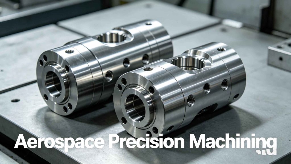
Here’s a real-world example that illustrates these principles:
Project: Aerospace mounting bracket, Ti-6Al-4V, 0.5mm wall thickness in places, ±0.05mm tolerance
Initial attempts elsewhere: 3 suppliers failed. Warping after final machining ranged from 0.15-0.4mm.
Our approach:
- Material verification: Checked billet microstructure and residual stress before accepting stock
- Modified stock prep: Stress-relieved incoming material at 650°C for 3 hours
- Balanced roughing: 8 roughing operations, alternating sides every pass
4. Strategic sequencing: Completed all external features before internal features
5. Conservative parameters: Reduced cutting forces by 35% vs. standard aerospace machining recommendations
6. Intermediate stress relief: Added 1-hour stress relief after roughing, before semi-finishing
7. Finish machining with support: Used sacrificial backer plate bonded with low-strength adhesive
8. Final measurement protocol: CMM measurement at 20°C, 24 hours after final machining
Result: First-pass yield: 92%. All parts within ±0.03mm after final verification.
FAQ: Common Questions About CNC Part Warping
Q: How long does it take for machined parts to warp?
A: Most warping occurs within 24-48 hours after machining, as residual stress redistributes. However, some parts continue to change dimensions for weeks, especially with temperature fluctuations.
Q: Can we fix warped parts instead of starting over?
A: Sometimes. If warping is less than 0.1mm, we can sometimes flatten parts by:
- Spark erosion machining on convex surfaces
- Localized heat treatment
- Mechanical straightening (with risk of re-introducing stress)
Q: Does using better tooling really help?
A: Absolutely. Sharp, high-quality tooling reduces cutting forces by 20-40% compared to worn or inferior tools. For precision machining, premium carbide tooling with proper coatings is worth the investment.
Q: Should we machine before or after heat treatment?
A: Generally, rough machine before heat treatment, then finish machine after. This provides the best dimensional control. However, for critical aerospace machining applications, sometimes it’s better to machine completely before heat treating, then deal with the expected distortion.
Q: How do we know if our supplier is following best practices?
A: Ask specific questions:
- What are your cutting parameters for steel milling/turning?
- Do you use stress relief between rough and finish operations?
- How do you verify flatness/straightness?
- What’s your first-pass yield rate for tight-tolerance parts?
Conclusion: Winning the War Against Warping
Here’s the thing—warping in machined components isn’t inevitable, but it does require attention to detail throughout the manufacturing process. As a precision machining provider, we’ve invested years in understanding internal stress behavior and developing systematic approaches to minimize distortion.
The key takeaways:
- Understand your material—know the specific behavior of each alloy you’re machining
- Plan for symmetry—balance material removal whenever possible
- Control the process—optimize cutting parameters specifically for stress control
1. Use appropriate fixtures—match clamping strategy to machining stage
2. Verify continuously—measure at key stages, not just at the end
3. Consider heat treatment—for critical parts, stress relief is insurance worth the cost
Remember: The goal isn’t just to make parts that meet tolerance when they leave the machine—it’s to make parts that stay in tolerance through shipping, storage, and years of service.
If you’re struggling with warped parts from your current cnc machining service, consider partnering with a machine manufacturer who specializes in precision work and has documented processes for stress management. The investment in finding the right partner will pay for itself quickly in reduced scrap and rework.
Technical Appendix: Key Standards and References
- ISO 2768: General tolerances for machined parts (affects how much warping is “acceptable”)
- AS9100: Aerospace quality management standard with specific requirements for dimensional control
- ASTM E1928: Standard Practice for Estimation of Measurement Uncertainty for Determined Values
- SME Technical Papers: Ongoing research on residual stress in precision machining
- Worried About IP Theft? How to Protect Your Hardware Designs When Outsourcing CNC Machining
- Warped Parts Warped Machined Components: Preventing Internal Stress and Deformation in Custom CNC Parts
- Struggling with Unreliable CNC Suppliers? How to Vet a Custom Machining Partner for Long-Term Success
- How to Negotiate Better CNC Pricing: A Complete Guide for Low-Volume Buyers
- Overpaying for Tight Tolerances? 5 Ways to Specify the Right CNC Precision Without Inflating Costs

 French
  English
  Italian
  German
  Spanish
  Portuguese
  Russian
  Arabic
  Japanese